Chapter 3 Building: PsychoPy Builder Interface
3.1 Building the Posner Cuing Task experiment
Posner Cuing Task
Participants will see a fixation cross in the middle and one box to the right and one box to the left. A cue will appear in one of the two boxes followed by a GO signal in either the same box as the cue (valid) or different place as the cue (invalid). Time duration for each segment is outlined in the picture below. Participants will be asked to decide as quickly and accurately as possible if they see the GO signal on the left box by pressing the S key or the right box by pressing the K key. There will be a total of 20 trials.
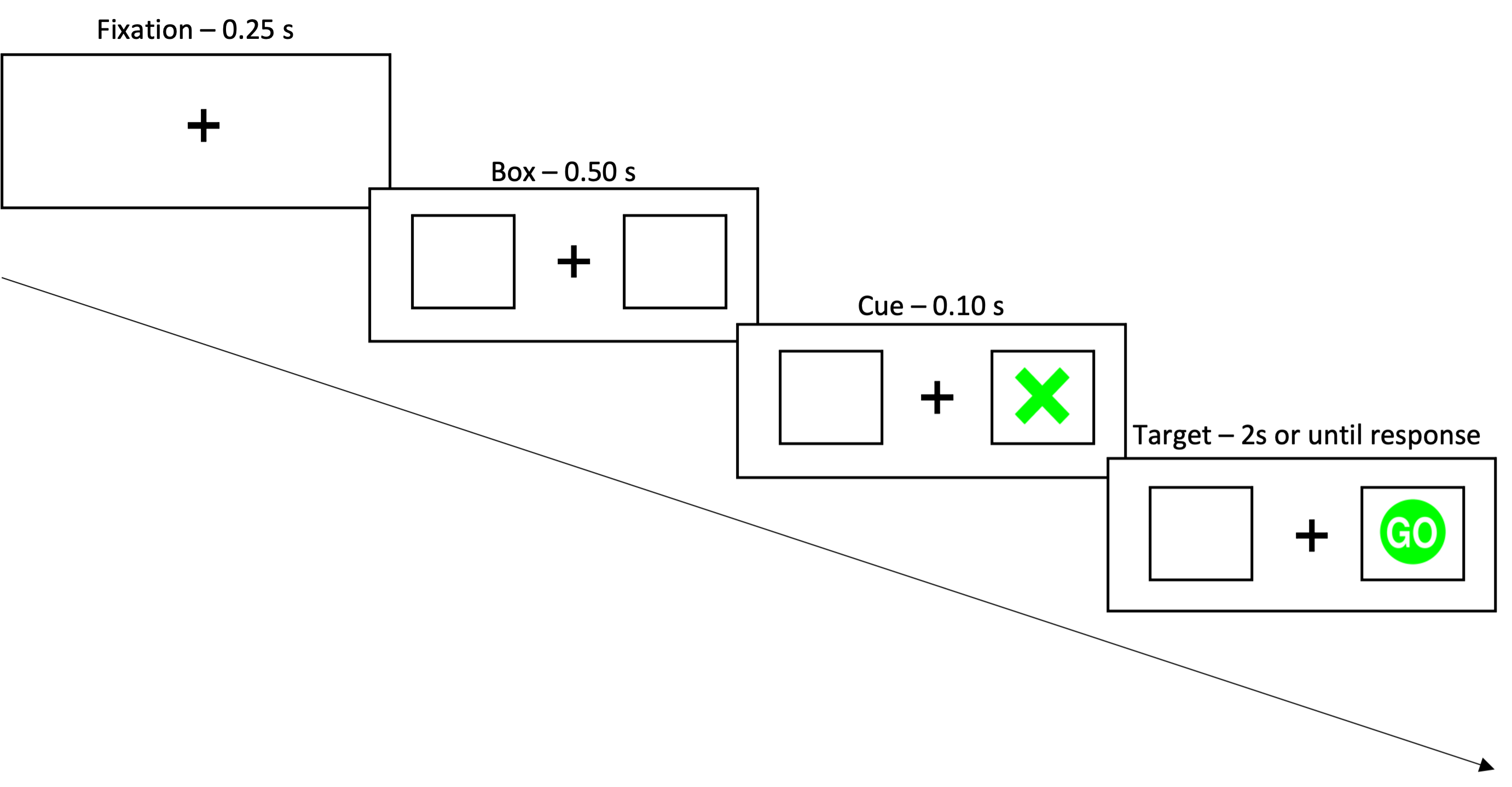
Figure 3.1: Time duration for each component of posner task.
If you are familiar with PsychoPy builder then stop here and try to create the experiment based on the description above. If not, move forward to see instructions on how to create this experiment.
Before beginning, it’s helpful to know a little bit about how PsychoPy builder works. PsychoPy builder uses excel/csv files to read condtion variables while the builder interface is used for static components, and flow of your experiment. In the excel file, each column represents a condition variable, and each row represents a trial. It’s best to create a separate folder for the experiment to contain all parts together (excel file, images, .psyexp file) for pathway consistencies.
3.1.1 Excel
Let’s start by creating the condition file on excel. For this task, we have three condition variables: condition type (valid, invalid), cue position (left, right), go signal position (left, right). We also have one extra column for the correct responses so we can track accuracy. The positions are represented in the units height, which scales everything relative to height of the window (best for online experiments).
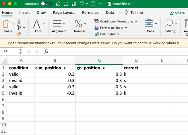
Figure 3.2: Condition file for Posner Cuing Task.
3.1.2 Builder
Now that we have the condition file ready to go, we can create the other components of our routine through builder. Let’s break down the task into a timeline of events.
1. Fixation cross appears from 0s to end of trial
We will use the Text component to create the fixation cross. The start of the stimuli is set at 0.0s and the duration is left blank to allow it to run until the end of trial. The spatial units should be set to heights, and the letter height needs to be adjusted from the default to about 0.08 height units.
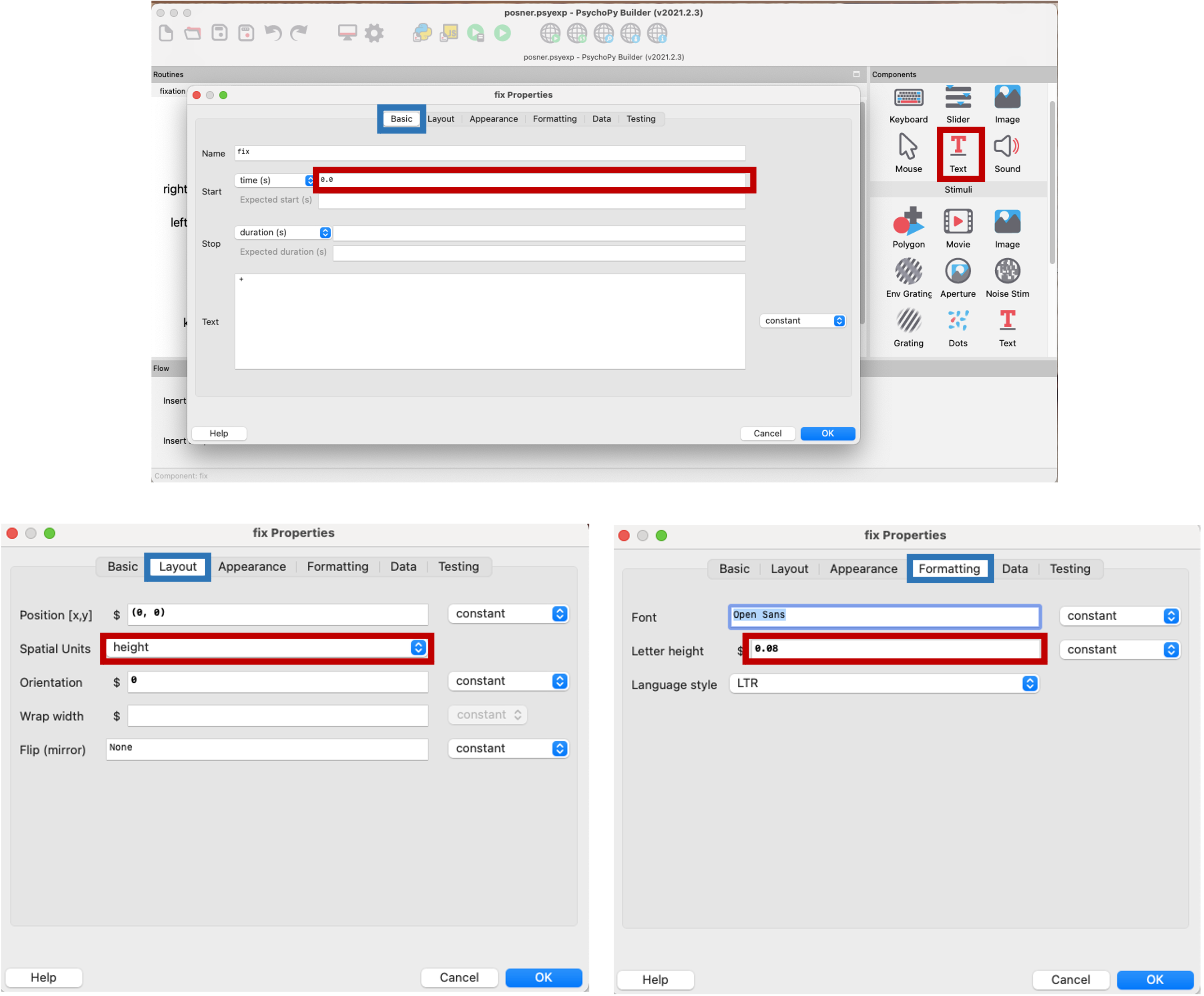
Figure 3.3: Fixation cross properties on builder.
2. Two box appears 0.25s after fixation (start time 0.25s)
Let’s start by drawing the left box. The start time is set to 0.25s, and we want to set the shape to rectangle for the boxes. The length and width is set to approximately 0.15 height units, and the x position is shifted to a negative value because it’s the left box. Remember that our boxes are need to be empty in the middle, and since we are not able to set a ‘transparent’ colour, we’re going to match the middle colour to the background colour (grey) to make it appear as transparent in the middle.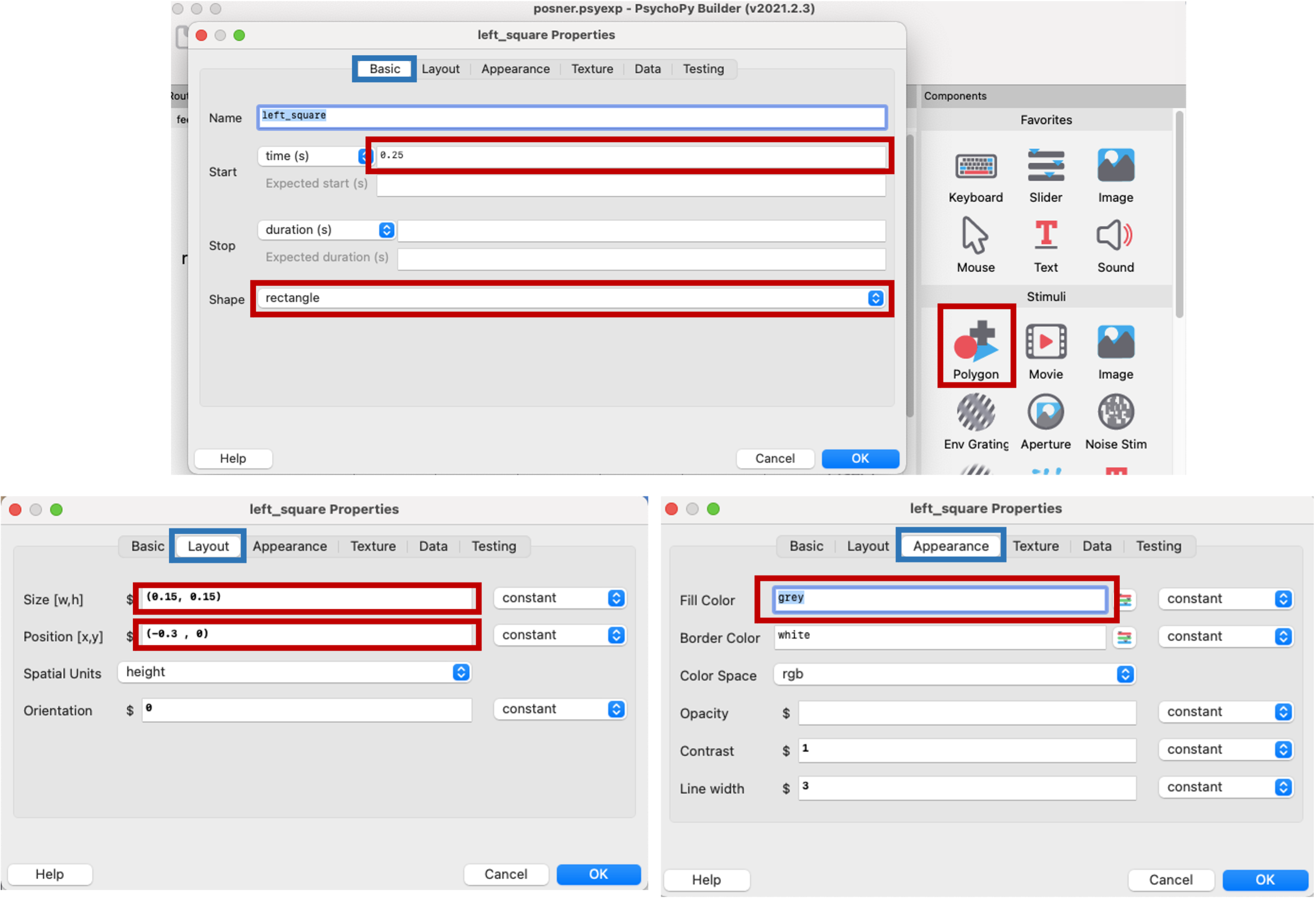
Figure 3.4: Left square properties on builder.
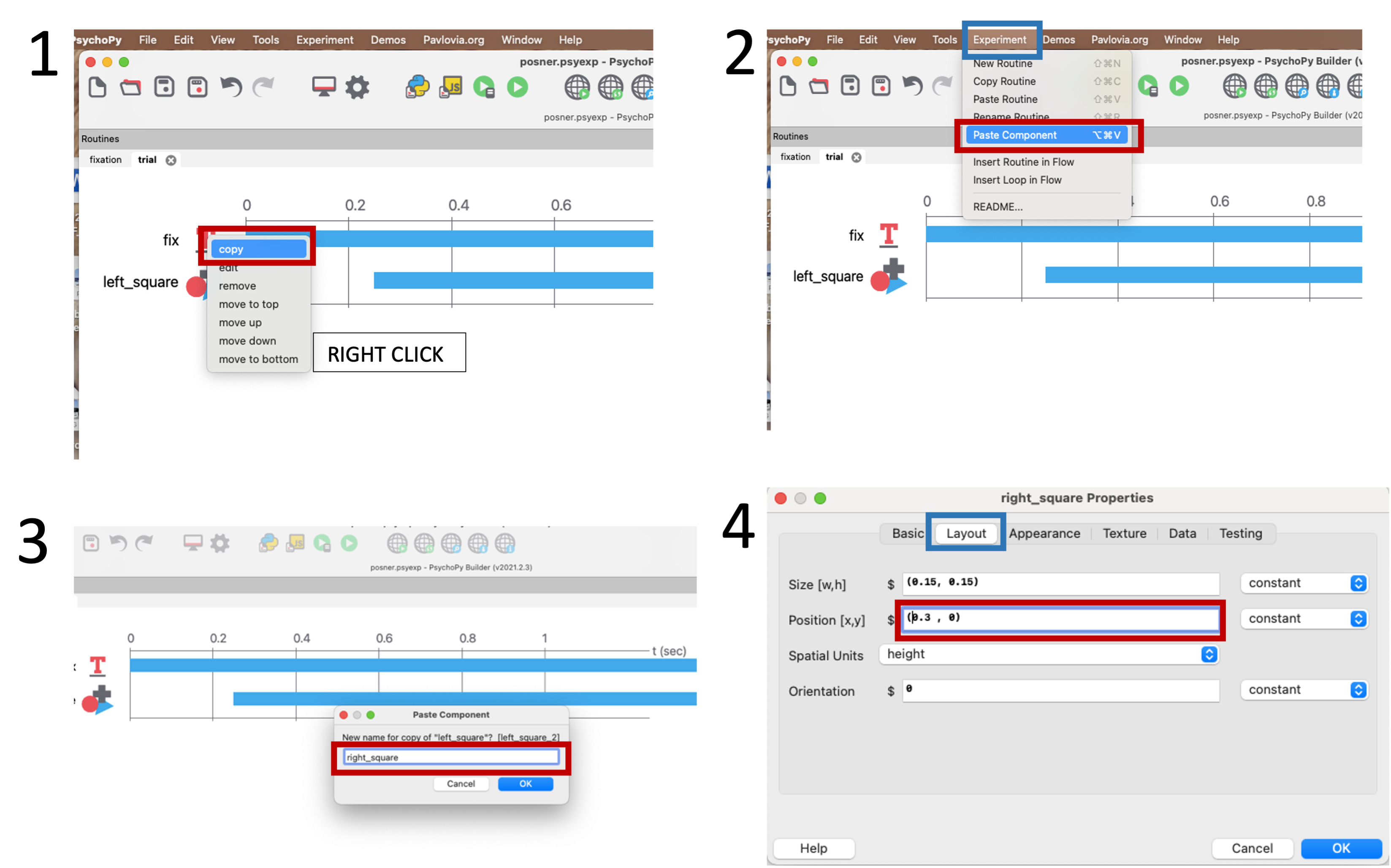
Figure 3.5: Copying left square to create right square.
3. Cue appears 0.50s after box (start time 0.75s)
Let’s create an image component to show the image of the cue. In our timeline, the cue appears at 0.75s and lasts 0.1s. In order to let PsychoPy know what and where the cue image is, we will paste the image pathway in the image box. The cue position variable is defined in the excel sheet, so we will put the name of that column in the x position box, and set it to repeate to indicate that it will update every trial.
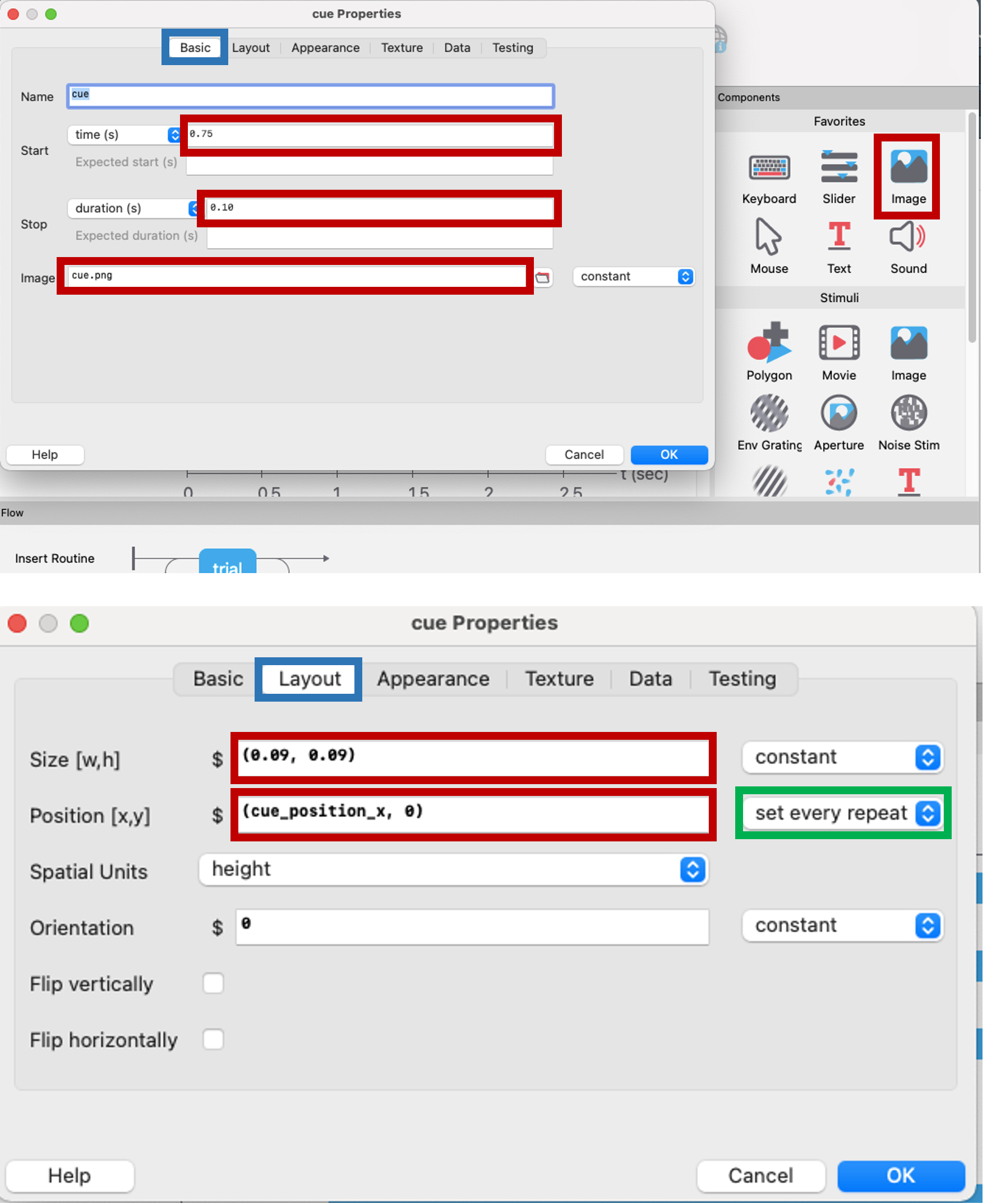
Figure 3.6: Cue image properties on builder.
4. Target appears 0.10s after cue (start time 0.85s), target duration 2s or until response
We will create another image component for the Go image. The properties of this component are shown below.
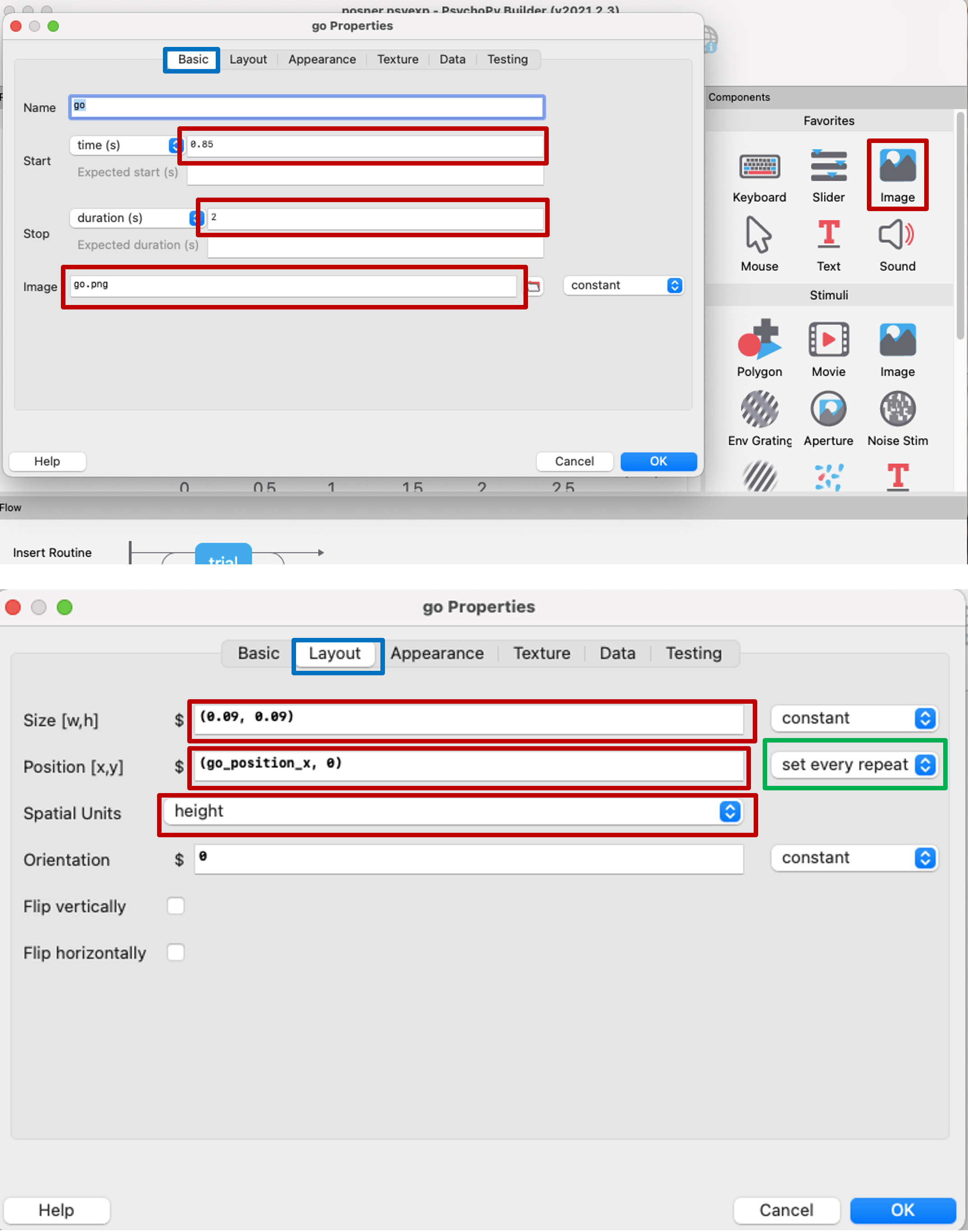
Figure 3.7: Go image properties on builder.
5. Record response key to end trial
To let participants make a response, we will use the keyboard component and set the allowed keys to ‘s’ and ‘k’. To keep track of the right answers, click on the option that stores correct answers using the variable ‘correct’ from the excel sheet.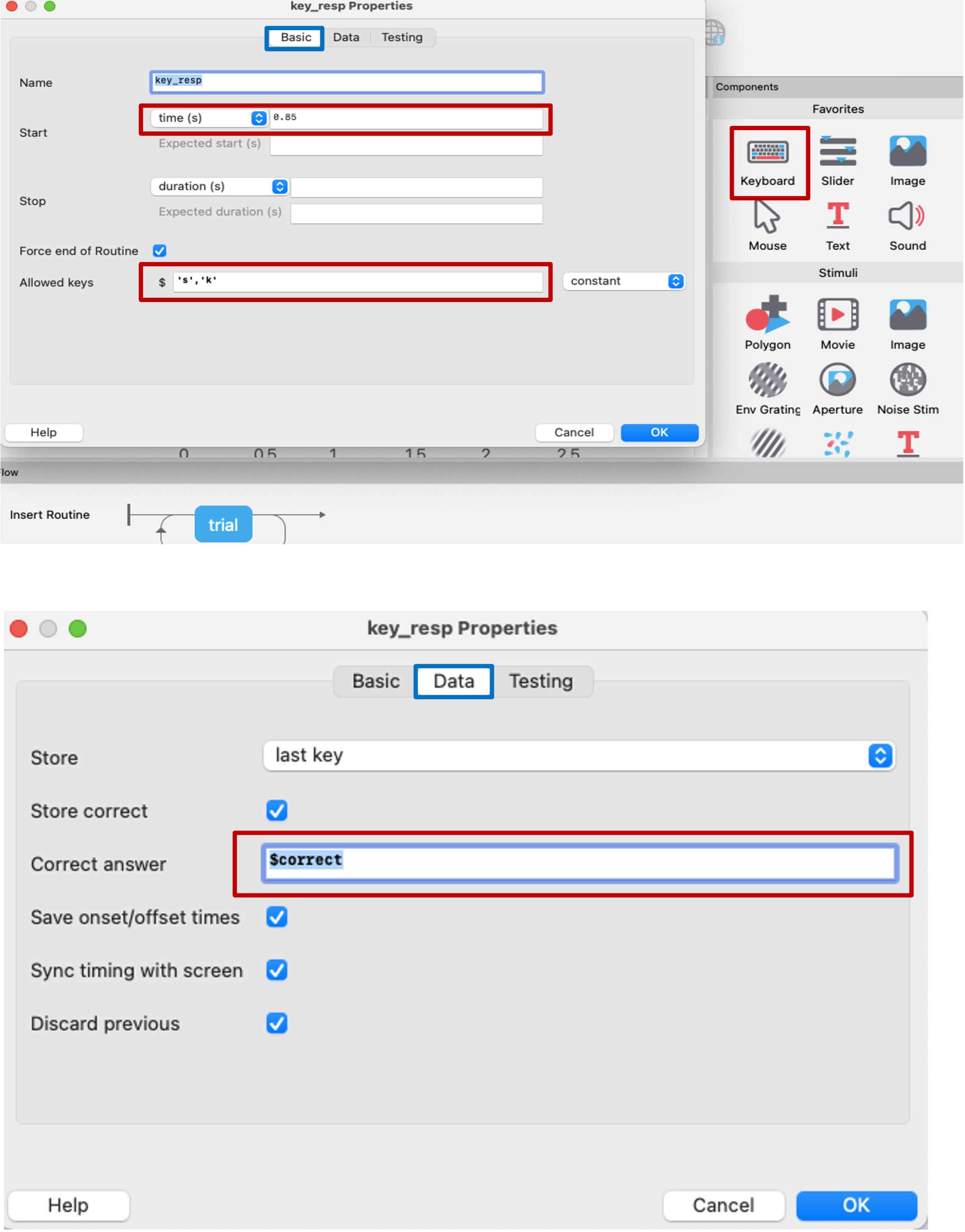
Figure 3.8: response key properties on builder.
3.1.3 Linking Excel to Builder using a loop
The loop allows us to randomize presentation of the conditions, and increase trial numbers. For this experiment, we have four trials in the excel file, repeated 5 times, resulting in a total of 20 trials.
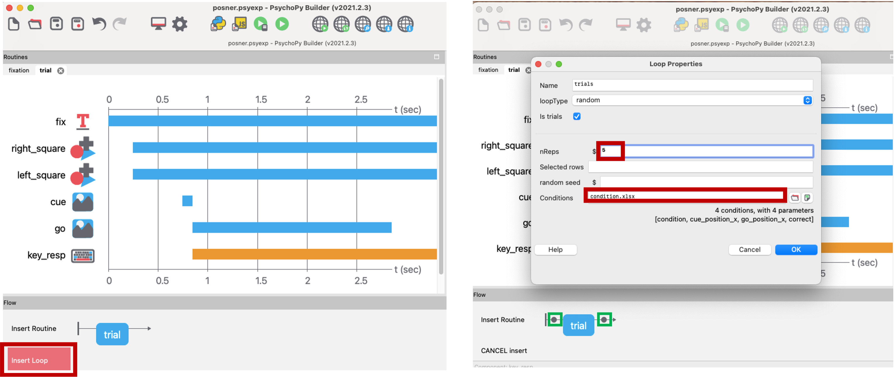
Figure 3.9: Routine flow and loop on builder .
3.2 Adding Practice Trials
For online experiments, it’s especially important to have practice trials to make sure your participants understand the task properly. Today we will be creating a practice trial that provides feedback after every trial, and doesn’t let the participant continue to the actual trial until they’ve gotten atleast 2 correct answer.
We want to have our practice trial contain everything our real trial has. To accomplish this, we will copy and paste the entire routine using Menu –> Copy Routine –> Paste Routine. Name this routine something meaningful like practice.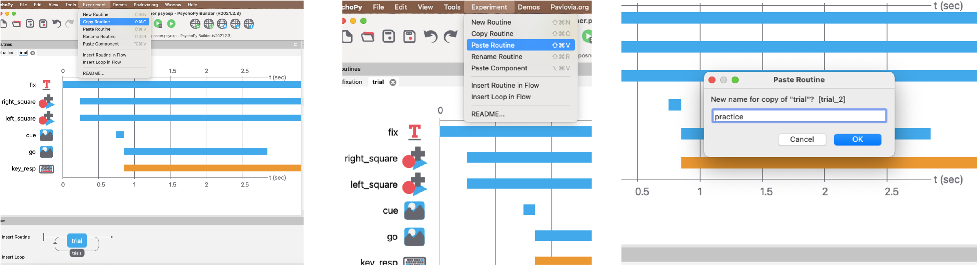
Figure 3.10: Copying trial to create practice routine.
Next we will create another routine called Feedback, which will tell the participant whether they got the trial correct or incorrect. This routine should be placed right after the practice trial. We will link these two routines to the conditional file using a loop. By setting the repetitions to a really large number, we make sure the loop continues on until we define when it breaks.

Figure 3.11: Creating feedback routine and linking everything to condition file.
Let’s return back to the practice trial and add a custom code component to define when the loop breaks (when participants can exit out of the practice trial). Under Begin Experiment, we will set the total accuracy number to 0 at the start of the experiment. At the end of the routine, we want to use a conditional statement that adds 1 to total accuracy everytime a correct response is made, otherwise, total accuracy stays at 0. Once participants gets more than 2 correct responses, we will end the practice loop (ending practice trials).
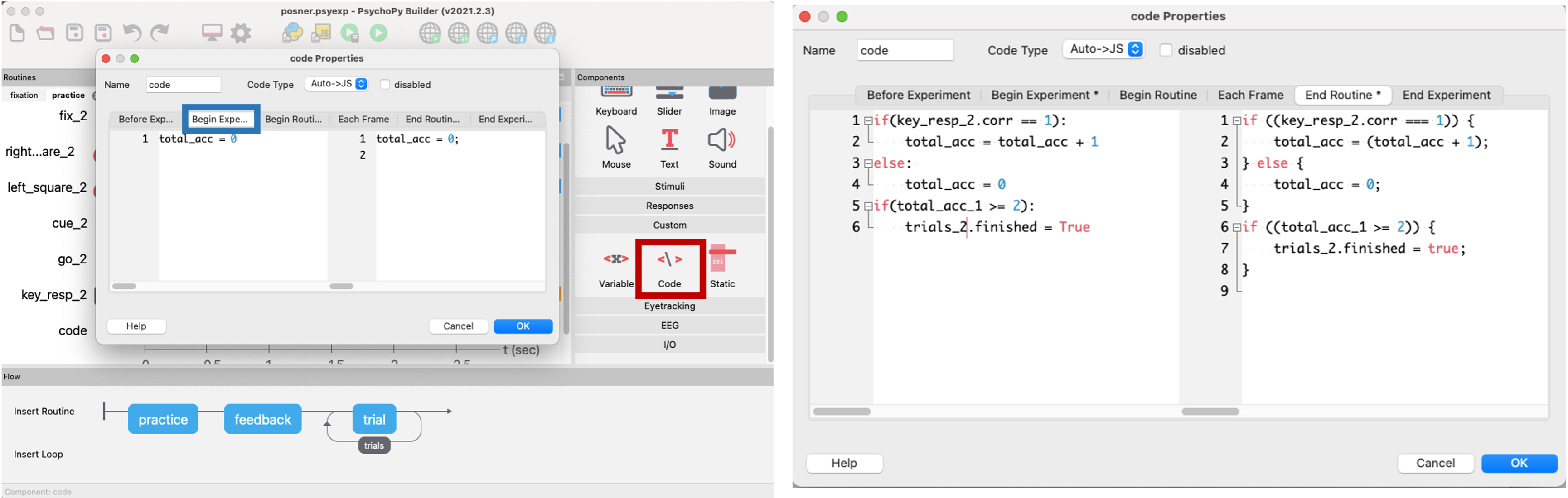
Figure 3.12: Code component for practice trial
Using this code component, we will define the message that participants get when they are doing the practice trials. In the begin experiment section, we first define the variable ‘msg’. In the begin routine section, we will use another conditional statement that checks whether the response made was correct using our excel sheet, and then displays the message “correct” or “wrong”.
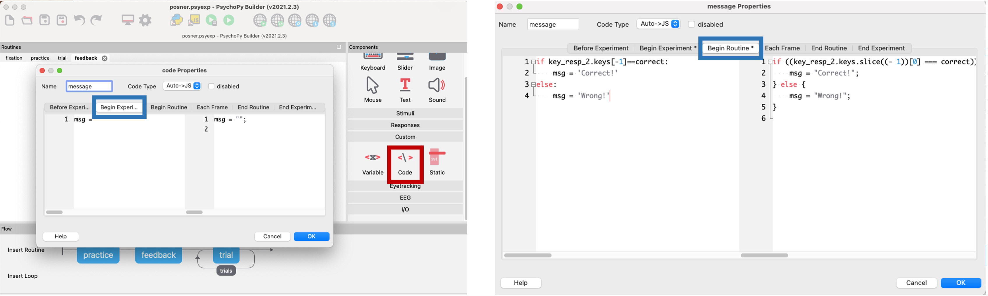
Figure 3.13: Code component for feedback message
The above ‘msg’ varible is shown for 1 second using a text component, set to repeat every trial.
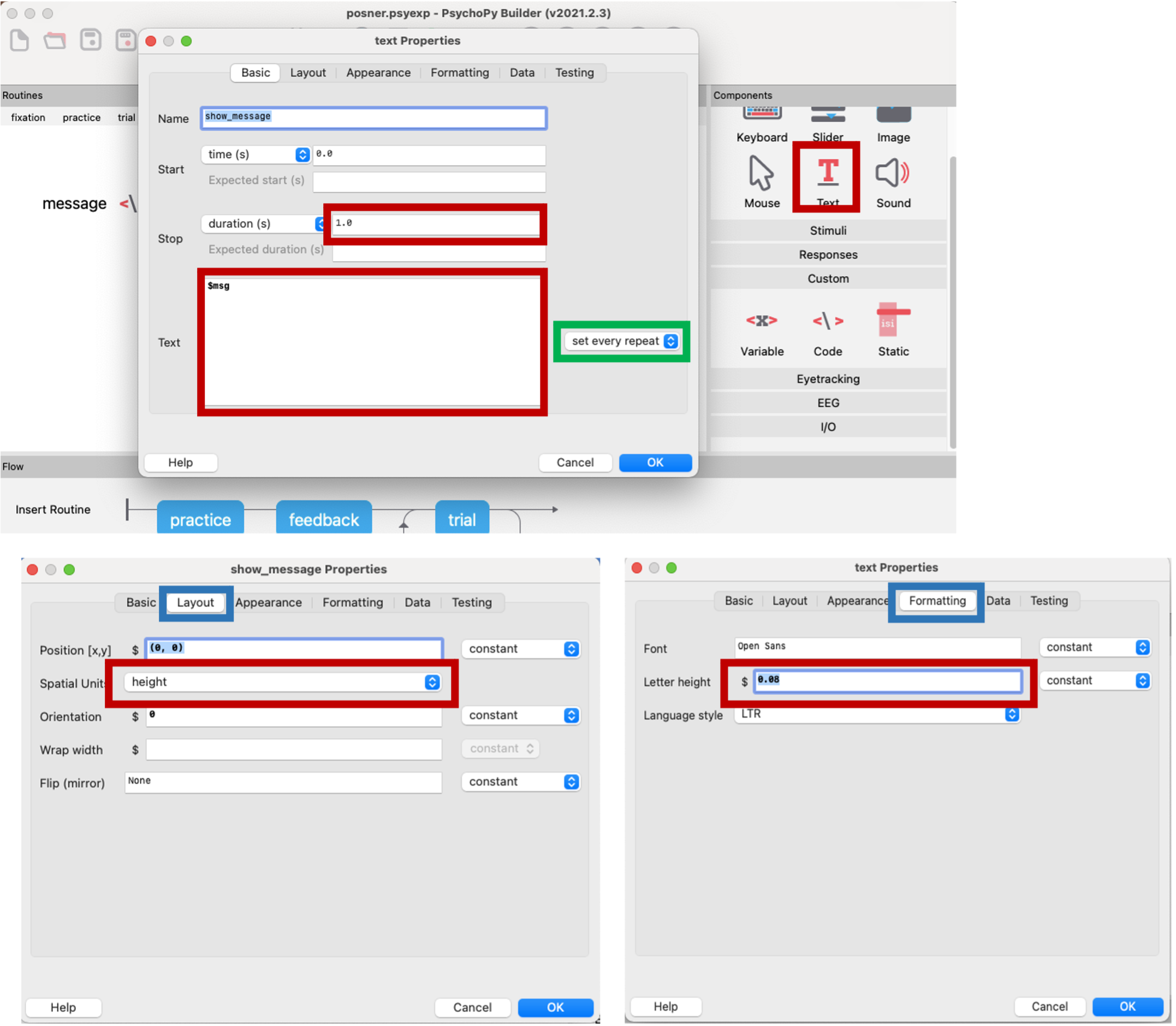
Figure 3.14: text component to show feedback message
3.3 Adding instructions, transition and goodbye screen
3.3.1 Instruction screen
Create a new routine called ‘Instructions’. In this routine, we will first add a text component which will show the instructions to the participants. Make sure to leave the duration of the component blank so participants get as much time as they need to read the instructions.
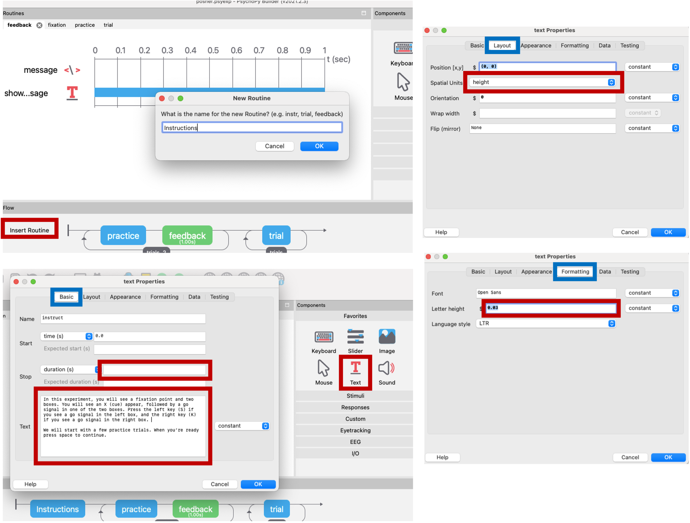
Figure 3.15: text component for instruction screen
To exit out the instruction screen, we will create a keyboard component that lets participants move forward to the practice trial by pressing the space button.
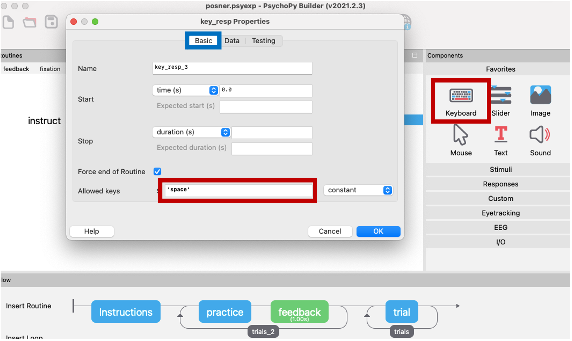
Figure 3.16: key component for instruction screen
3.3.2 Transition screen
After the participants finish the practice trial, we want a transition screen before moving into the actual trials for the experiment. This is done through another text component, but this time setting the duration to about 3 seconds to give them a chance to read.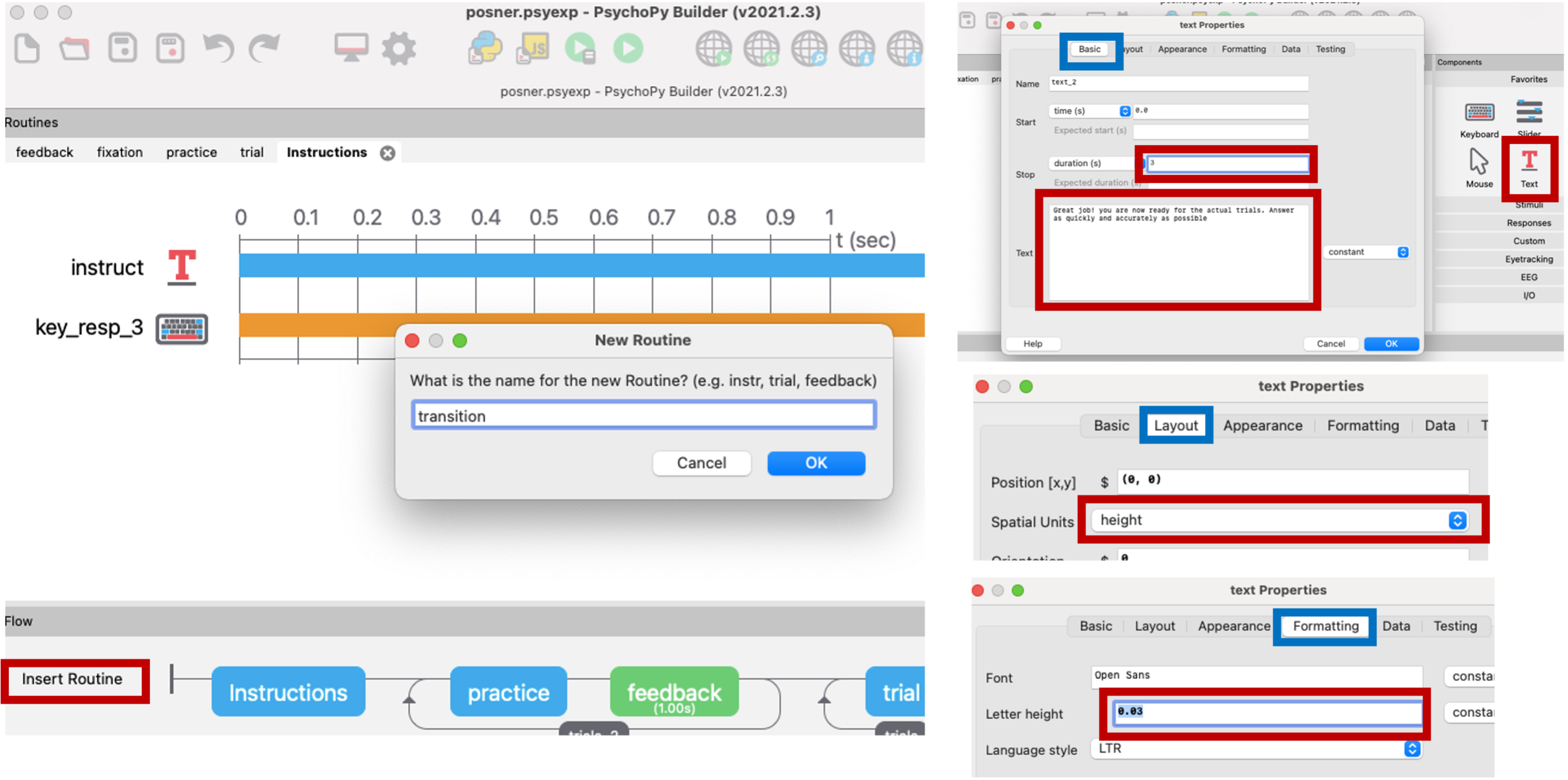
Figure 3.17: text component for transition screen
3.3.3 Goodbye screen
We will end with a goodbye screen to let participants know they have finished the trial. This can be achieved with another text component with duraiton set to about 2 seconds. Don’t forget to change the units to heights, and the formatting to 0.03.
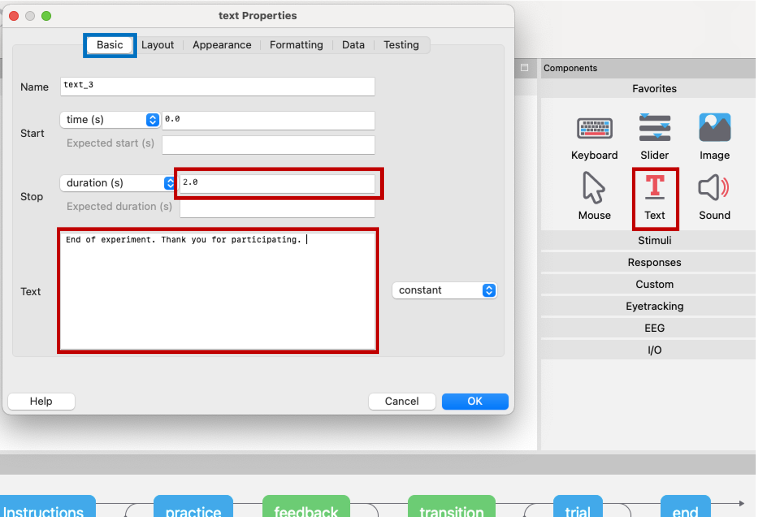
Figure 3.18: text component for end screen